|
|
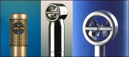
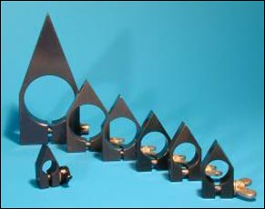
Vane Wheel Flow Sensors FA |
|

|
|
|

|
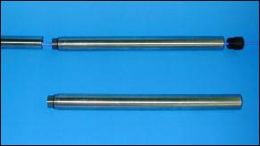
Flowtherm cylinder probe FT
Insertion probe with integrated Pt100 probe for measuring temperature |

|
|

|
|
|

|
Special specifications |

|
|

|
|
|
such as cylinder probe with protective mesh or T-probes for achieving
a higher rate of indirect oncoming flow indifference |
Types of cylinder probes |

|

|
|
|

|
initial smallest measurable flow rate dependent on type of vane wheel:
in gases 0.2...1.6 m/s; in liquids 0.01...0.08 m/s |

|
|

|
|
|

|
terminal flow rate dependent on type of vane wheel:
in gases 3 m/s; 20 m/s; 40 m/s; 80 m/s;120 m/s; in liquids: 3 m/s; 7.5 m/s; 10 m/s; condition: no cavitation |

|
|

|
probe diameter: 14/15 mm; 16 mm; 18 mm; 18/20 mm; 25 mm; 25/27 mm and 30 mm |
|

|
|
|

|
working temperature range: up to +100° C; +140 °C; +260 °C; +370 °C; +450 °C and +500 °C |
|

|
|
|

|
maximum working pressure: up to 25 bar overpressure |
|

|
|
|

|
explosion-proof type of protection: Category 1G and 1D Zone 0 and Zone 20; Category 2G and 2D Zone 1 and Zone 21 |
|

|
|
|

|
probe tube material: aluminium, stainless steel, titanium |
|

|
|
|

|
special designs on request |
Accessories for cylinder probes |
|
|
|
|
|

|
probe tubes/extension rods for screwing onto extendable
cylinder probes |

|
|

|
|
|
|
|

|
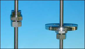
probe guide pieces with flange or screw thread connection for installing cylinder probes in pipelines and ducts |

|
|

|
|
|
|
|

|
direction indicator for clamping onto the probe tube;
may also be used as a depth indicator |
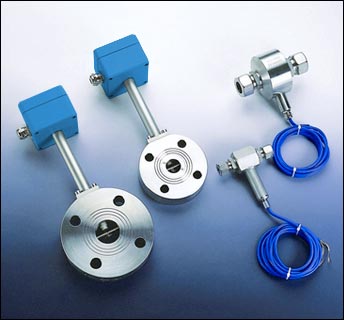
FA・Di measuring tubes |

|
for recording volume flow / flow velocity |

|
|

|
FAR・Di |

|

|
|
|

|
for measuring volume flow/flow velocity
for ± direction sensing |

|

|
|
|
|

|
Special specifications |

|
|
|
|
|
also available with integrated temperature
probe Pt100 and / or built-in absolute pressure gauge |
Types of FA・Di measuring tubes |
|

|
measuring tube inside diameter: 9.7 mm; 18.2 mm; 25 mm; 32 mm; 40 mm; 50 mm ... |
|

|
alternative forms of connection depending on inside diameter of measuring tube:
tube fittings; cutting ring fittings; flange connection;
flat tube ends; internal screw thread for connecting nipples |

|
|

|
alternatively with / without input / output section |
|

|
initial smallest measurable flow rate dependent on type of vane wheel: in gases from 0.08 m3/h,
in liquids 0.007 m3/h |

|
|

|
terminal flow rate dependent on type of vane wheel: in gases 20 m/s; 40 m/s; 80 m/s;120 m/s;
in liquids: 3 m/s; 7.5 m/s; 10 m/s |

|
|

|
working temperature range: -20° C...+100 °C; -20 °C...+240 °C and above |
|

|
maximum working pressure: up to 25 bar above atmospheric |
|

|
materials: stainless steel; PVDF; aluminium ... |
|

|
explosion-proof type of protection: Category 1G and 1D Zone 0 and Zone 20; Category 2G and 2D Zone 1 and Zone 21 |
|

|
special designs on request |
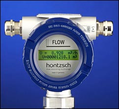
Transducer UFA integrated in Ex-d sensor connection housing |
|
|
|

|
integrated transducer in Ex-d sensor connection housing for vane wheel flow probes FA / FAR or measuring tubes FA Di |

|
|
|

|
Hart interface for changing the calibration and parameter data |
|
|

|
Ex-protection: Category I Zone 0 and 20, Category II Zone 1 and 21 |
|
|

|
analog output: 4-20 mA |
|
|

|
relay output optional for flow direction, limit value or quantity pulse configurable |
|
|

|
optional LCD display for instantaneous value and counter |
|
|
|

|
power supply: 24 VDC |
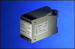
Transducer UFA / LDG16 |
|
|
|

|
Configurable digital transducer |
|
|

|
for vane wheel flow sensors FA with and without
directional sensing |
|
|

|
PC interface for changing calibration and parameter data analog output: 4-20 mA, 0-10 V; optional |
|
|

|
relay output optional for flow direction, limit value or quantity pulse configurable |
|
|

|
power supply: 230 VAC; 24 VDC and 12 VDC; optional |
|
|

|
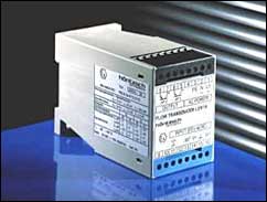
design: LDG16 surface mounting housing (W/H/D = 55/75/110) for 35 mm
standard assembly rail |

|
|
|

|
conversion from actual to standard flow velocity
or, alternatively, flow rate |
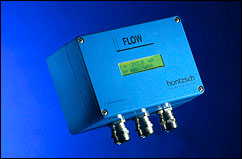
Transducer UFA / AS102 |
|
|

|

|
|
|
|
|

|
Configurable digital transducer with IP65 type of protection |
|
|

|
for vane wheel flow sensors FA with and without directional sensing |
|
|

|
PC interface for changing calibration and parameter data analog output: 4-20 mA, 0-10 V; optional |
|
|

|
relay output optional for flow direction, limit value or quantity pulse configurable |
|
|

|
optional LCD display with instantaneous value and counter |
|
|

|
power supply: 230 VAC; 24 VDC and 12 VDC; optional |

|
|
|

|
design: aluminium housing AS102 IP65 (W/H/D = 100/75/110 mm) |
|
|
|

|
conversion from actual to standard flow velocity
or, alternatively, flow rate |

|
LDX1A / LDX2 |
|
|
|
|
|
|
|

|
isolation/supply unit for connection of vane wheel flow sensors FA with and without direction sensing in EEx ia IIC T6 type of protection |
|
|
|

|
|
|
|

|
operation only permissible with non-Ex evaluation units: transducer U1a or transducer U2a or system instrument in LDG30 housing (see below) |
|
|
|

|
|
|
|

|
LDX1A ATEX and secondary evaluation unit are to be placed in a non-hazardous space |
|
|
|

|
|
|
|

|
power supply: 230 VAC, 24 VAC; optional; DC supply with series connected DC/AC converter possible! |
|
|
|

|
|
|
|

|
LDG16 miniature housing (W/H/D = 55/75/110) for 35 mm standard
assembly rails |
|

|
|
|
|
|